June 2016
The final cross coats of silver went on without problems and the fuselage is ready for top coat. However given the problems I had with the tail-feathers I stopped painting until I'm sure all the problems have been solved.

seal the firewall
By the way, this syringe came from a Locktite product that I can't remember. It appears to be made of polypropylene and nothing sticks to it. I'm so glad I hung on to it because whenever I need to run a neat bead of sealant, I mix up a small batch, put it in the syringe (with a tongue-depressor) and apply sealant, usually without having to mask things off.
Whatever sealant is left, gets left in there until cured, then I pop it out with punch or 3/16 rod.

Once the crinkle paint is removed the instrument panel looked bent. It was.
Fortunately the soft relatively thick material responded well to my knockometer and shrinker and is back in good nick.

I experimented with some scraps to see how to form the map box doors. The ones I had were 063" flat plates.

I got the dimensions from measuring the fretting marks left by the original doors, made some forms from plywood, and hammered out two nice doors from 6061 T6 040".
This was so satisfying, I made some more just in case anyone out there needs one.


 So that the door completely covers the opening in the instrument panel, the hinges are formed like this....

Following my strategy of trying to install or at least test fit everything that is easier without fabric on the fuselage, the last two items were the wire "bundle" and the headliner. The former was easy as the wiring for a non-electrical Tcraft consists of two antenna coax cables and the ELT remote wiring.
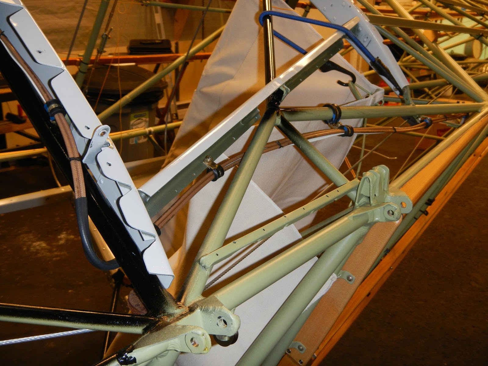
Now onto the headliner. You may recall I had to make a template out of an old sheet, which was then sent to Aircraft Spruce. The replacement headliner had many "loose ends" pardon the pun including closing pockets for the three bow supports, re-stitching the rear "bulkhead" area, figuring out how to attach the entire perimeter, and fabricating wood and aluminum trim.

I remember thinking "how the hell am I going to do this!"
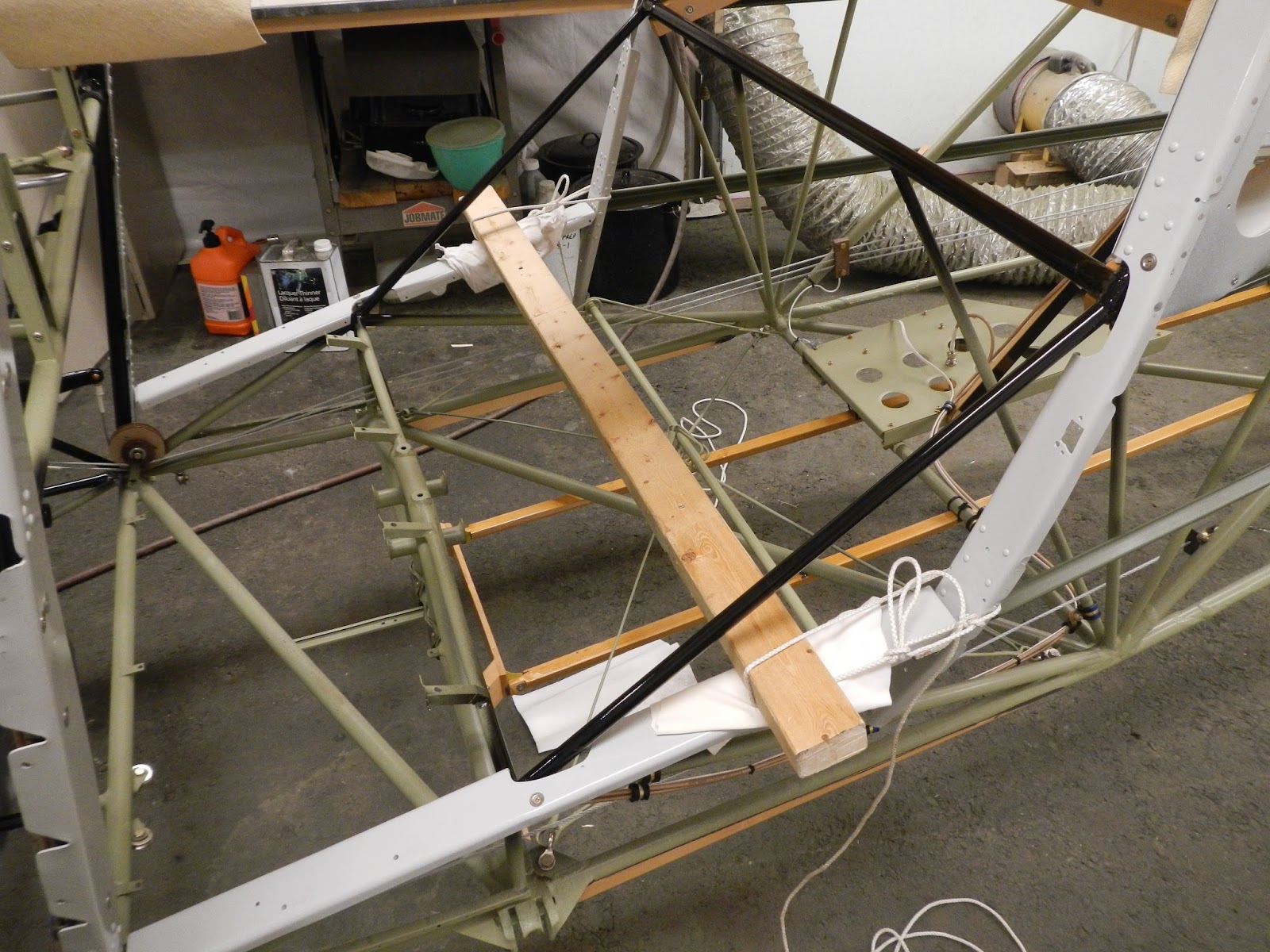
Fitting the headliner is a tense task. One wrong snip and the headliner could be junk. This awareness meant that I spent as much time second-guessing myself as I did actually fitting.


Although I hadn't intended to fabricate wood trim, it turned out to be the preferred solution. The windows will be through-bolted to the aluminium frame ( before fabric) and the wood trim will pickup the machine screws and held in place by cap-nuts.
Originally the windows were installed with PK screws. More on the solution I choose later.

The top to rear panel (bulkhead) needed to be restitched down to the window frames. Pins wouldn't hold so I actually had hand stitched it in situ, then machine sewed it once removed.

Two pieces of 3/8" sitka spruce were found in my bundle that were just big enough.
With the newly fabricated trims clamped in place and the rear strip attached, it appears possible to get a decent result.
The areas around the aft door frames were particularly difficult but eventually were trimmed and sewed to form around the posts.

So I came up with this variation to finish off the top corners
 Eventually these will be painted and possibly covered in either glare-shield black fabric or headliner leftover.
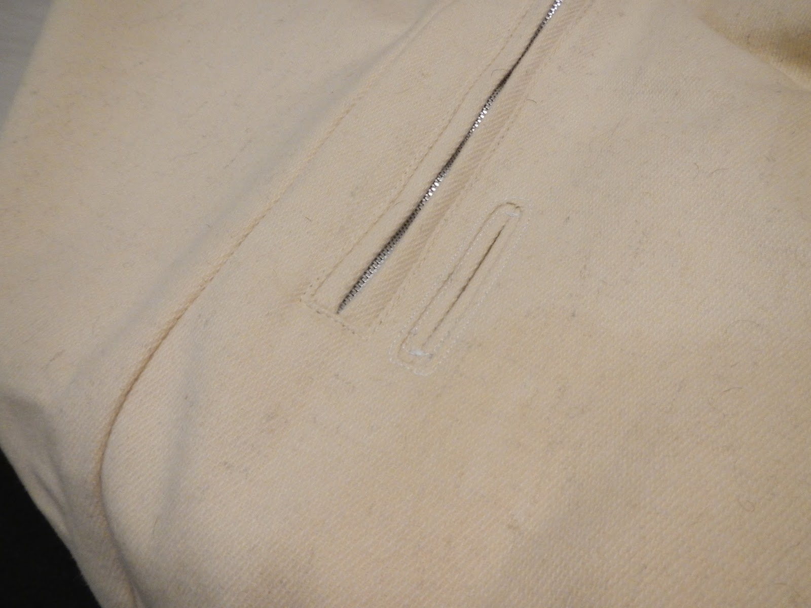

 |
| Looking better |


Here are the highlights of the fuselage covering process along with some images that I just thought were interesting.
I did not use a sock based on what I'd learned at Oshkosh and the Polyfiber workshop.
 So first the bottom was covered. This was pretty straightforward and left me feeling optimistic in regard to progress.

Once at the shrinking stage, I shrunk the fabric evenly around the fittings such that the fabric remained snug around each.


The manual says 225 degrees for heat forming and smoothing the glued edges and tapes. To be honest I'd still be smoothing if I hadn't cranked it up to 250 and more in many instances.
The iron gives up heat quickly, especially when there is a steel tube keeping the fabric cool. The key is to get the fabric to 225 and get it to 250 only when you want shrink. Unless you have all day, the iron must be hotter than 225 to be effective. The variables are the amount of time the iron is in contact with the fabric, and the substrate. I glued a piece of fabric to an old fuselage tube and practiced a while. In the end most of the heat forming and smoothing I did with the irons at about 275. This considerably improves the effectiveness and speed of the process. It also significantly increases the risk of a screw-up if you leave the iron in contact too long!


I choose to take the shortest route. Worked out ok but I was asking a lot of the fabric to shrink around the inside corner of the fin transition.

The ghost in the machine....
 Tricky to get a good result when the fittings are close together. Fortunately the fabric is strong so you can pull hard and a small cut will "stretch" over fittings etc.
 Fin top is heat formed just like the controls

 Though not too visible, I took my time trying to get a straight line where the side fabric overlaps the bottom. Good practice for the top!
 Necessary to disconnect the tail stand to attach the fabric at the rudder post. Bar stool makes a good substitute.
 Same procedure as for the flight controls. Line is penciled half the the finishing tape width from the centreline of the tube, fabric is trimmed to the line, then glued to the line. Once the adhesive sets up a bit the iron is used to smooth things out.

The fabric is shrunk evenly on both sides of the fin and straightedge used to monitor the progress and keep things straight.
Now for the tricky top panel...

 Fabric is folded back on itself and glued with Poly Tak. Then I marked the location of the stitches
 Then baseball stitching to close it up. I thought it looked good.

Then I found an addendum to the manual and although the drawing shows a 3/16" dimension between stitches, the text says 3/16" to the edge of the fabric. SH**$%!!!!
I had read the Poly Fiber manual cover to cover several times and never picked up on this little gem. It was actually AC43 13 that put me on to this while I was looking up something else.
 So the joint ended up being double stitched. hopefully it won't look too "Frankenstein" through the topcoat. The important thing I'm more than confident the joint is strong!

So the basic cover went on well and certainly creates the appearance of progress. Next comes doilies, gussets, and tapes (where progress is much less apparent :)

 First coat of Poly Brush
 Inspection covers need to be fabricated,

and the frames to which the fabric is attached and ultimately fasten the covers.
I had one elevator access cover that appeared to be original so I copied that for both sides.

I used 2024 T3, 025" for the covers and 032" for the frames.
As can be seen, in place of leaving the bottom of the frame open (as the original plastic ones were) I kept a full frame which will be attached to the longeron with the gusset/doily and Poly Tak to add a little more stability.
 Frame is formed to sit snugly on the fabric
 Ready for primer
 While I was at it I made the aileron bellcrank inspection covers and frames as well.
 and the frames are attached with Poly Tak just like the inspection rings

Gussets for the lower strut attach points
 Poly-brushed in place.
 and several of these for the wing attach structure.
 Poly tacked in place prior to installing the finishing gussets.

 Shining a flashlight through the aileron cable fairleads yields the location where the cables will penetrate the fuselage fabric. Typically there's just a hole or slot (or worse) in the fabric, and the Poly Fiber manual is silent on this sort of thing other than the stipulation that 1/4" drain holes are acceptable as long as there is at least two layers of fabric. Anyway I used my fly-cutter to make these 025" washers for the cable openings.
 cemented in place with Poly Tak

After ensuring the fabric is well glued to the frame, the window openings are opened and fabric folded back and Poly Taked.

An aluminium oxide disc works well for cutting Plexiglass.
 Oversize holes are drilled with a 5/32 bit sharpened with a shallow angle on the flutes.
 There is a slight compound curve required for the baggage compartment windows. A strategically placed weight coupled with a little heat and a couple of hours did the trick.
The holes are carefully coutersunk to accommodate tinnerman washers, and the surface is sanded with 320 grit to aid adhesion..
 Important to torque the screws only enough to hold the window just snug.

Pre-shrunk light fabric is used to make the finishing gussets

and Poly Brushed in place.
I decided to use this method of attachment because examination of the old windows and frames indicated this was how it was done originally (with PK screws in place of the machine screws). It also achieves a better result in terms of appearance and surface smoothness. If the window ever needs to be replaced, an aluminium frame can be used in place of the fabric gusset.

I went to our local Canadian Tire in search of a straightedge to aid in 1" tape installation. I had a 1 meter construction ruler (yardstick) in my hand and for some reason picked up a second and placed the two side by side.... Neither was straight. None of the others on the shelf were either! Perhaps I'm at fault for believing a ruler should be straight?
Anyway, on the next isle I picked up a 1" by 1/8" aluminium extrusion which was less money and straight, and actually worked very well for marking the location of the stringer tapes.

The next several days were spent installing various tapes, gussets, and doilies.
At the Poly Fiber workshop at Oshkosh it was suggested that the second coat of Poly Brush can be sprayed on prior to installing the dolies, gussets and tapes (in lieu of precoating by brush), and I had planed to do this. But in the end I choose to take my time, dealing with all the fiddly bits. I can see that this (sprayed precoat) is a time saver however and will use it when it comes time to do the wings.
 There's no rush when applying tapes. Best to do a little at a time, make sure they're straight and go down wet.
 Wrinkles and bubbles are ignored until the Poly Brush is dry,

Then easily taken care of with the iron.
 For the front top edge I used a 3" tape and attached it to the front face first.
 Then heat-formed it over the curved carry-through form, and marked a straight pencil line.

Tape is then cut along the line with pinking shears,
 and secured in place
 My technical drawing kit proved very useful. The small compass with little allen key installed in place of the point was great for pulling lines parallel to longerons, leading and trailing edges.
 3" tapes are required for the fin to fuselage joint.
 Fin leading edge is precoated in preparation for a 3" bias tape
 Tape is trimmed down to about 1 1/2" and attached at the leading edge
 then the inside radius of the fin transition is attached

Just a little tension is applied to the tape as the centreline is secured to the fin leading edge

a minimum of heat forming is required to get the tape to lay flat.

The trailing edge is done in two sections. From the inspection panel up is a 3" tape, and the lower half is done with a 4" tape cut after heat-forming in a similar fashion to the front spar carry-through. The objective of course is to achieve a straight line even though the tape width varies to accommodate the rudder stops and longeron attach point.

The fuselage has two low points so two drain holes are provided.

Eventually I'll find out if my measurements were correct for the Rudder cable feed-throughs
 For now I'll have to trust myself
 Dollar patches are applied at the fuel valve location

and trim crank location.
 Last thing before the spray booth is to open up and secure the elevator inspection access.
 Fabric is heat-formed and then cemented with Poly Tak

The desired result is achieved with the full frame attached to the upper fuselage longeron.

After a full day with the iron, smoothiing out edges and tapes etc., the second coat of Poly Brush is sprayed on
 and the final coat of Poly Brush the next day.
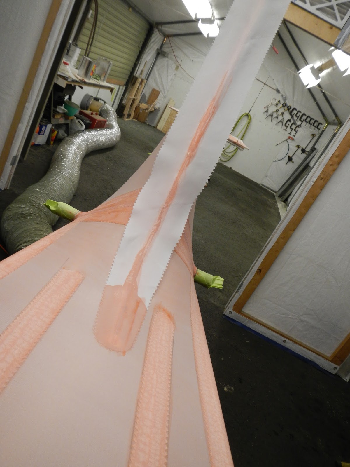
 First cross-coats of Poly Spray, followed by a couple of hours with the iron to secure tape pinks, small bubbles etc.
 Next day the second cross-coats are sprayed, followed by wet sanding.

All the remaining little blemishes are wet sanded with 400 grit paper as well as the edges of all the tapes, gussets and doilies, and any place where significant sanding is needed is recoated with PolySpray.
Fuselage is now ready for the final cross-coats of Poly Spray.

Between coats I took care of some other tasks. I'll need the inspection plates and other small parts to use up any mixed top coat so they need to be ready.

Also finally got around to riviting the boot cowl together

With some new camlock springs.
October 2015
Continuing to install various parts on the fuselage prior to commencing the covering operation. Basically anything that can be installed or at least fitted prior to fabric is a little easier at this stage.
 New Aileron cables are made by duplicating the originals, but first, decades of gunk was cleaned from the chains.
 Cables ready to install after the chains are soaked in chain lub/wax.

To install and rig the cable assembly, I need the control shafts and wheels. One of the phenolic bearings was ok but the pilot's side was worn to the point where the control wheel was sloppy. Fortunately I had a piece of 1/4" phenolic I've been saving for just this purpose.

Shafts installed temporarily

It was bound to happen.... I needed to open up one of the pulley mounts a little to accept the new pulley and when I did the weld broke. One of the nice things about TIG is a small weld like this can be done without negative effects to the surrounding components.
Wheels, shafts, sprockets, pulleys and cable assemblies installed...


...and tensioned.
Because of the configuration of the control 'H' frame and cable pulleys, aileron cable tension changes depending on the position of the elevator control. Rigging therefore consists of centering the control wheels, centering the bridal link and setting minimum cable tension with the elevator in the mid position. The result is a max tension of about 20lbs with the elevator in the full up or down position, and a minimum of about 5Ibs at the mid point.
 To fabricate the fuel line for the aux tank, the main tank needs to be in place.
 So the paint is removed and, tank inspected,....and a successful pressure test.

Also needed is the shutoff valve. Both are rebuilt at this time.

 The replacement fuel line follows the original routing and adel clamps hold it securely so no possibility of chafing

or interference with the aileron cable.
The mount, fabricated earlier, is secured in place and replacement fuel line attached.

I was missing one of the four shackles that holds the seat "spider" and managed to find one at Oshkosh. Not that these are particularly difficult to find, but they're not inexpensive! Anyway I got a good price and saved on the shipping (that is of course if we consider my flight to OSH as a sunk cost :)

The side rod on the left is about an inch shorter (due to the fuselage diagonal) than the one on the right, and it's easy to mix them up resulting in a crooked seat!
Note also that the seat-belt attachment and support rod go around the cross-tube and not just the loop. (This is important!)
 This lovely piece of maple was what was installed, and I had sanded and refinished it, but it is not the correct installation. It is supposed to be bolted to the top of those supports. I did manage to re-purpose the maple though
 I purchased a seat sling but I'm not impressed with how it fits. In fact my tape measure revealed it is not even symmetrical left and right and as can be seen here it doesn't really fit nicely around the rear cross tube. I've been in touch with the supplier and they are responsive albeit slow. To be continued....
The hat shelf needs to be covered before installation so thanks to Thunder Bay Aviation I sourced some excellent quality glare shield fabric

 Fabric is attached with 3M hi-tack and then I can't resist the urge to offer up the spruce headliner trim:
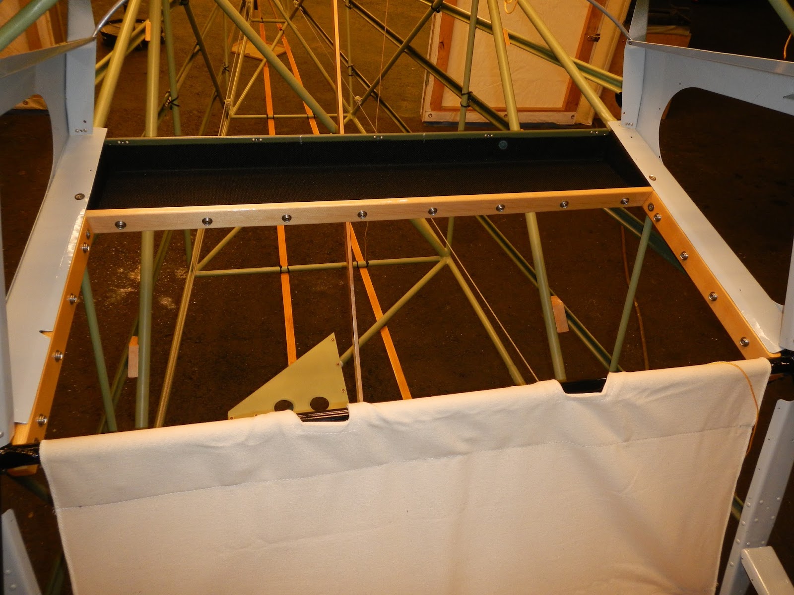
 I lay out and install the baggage compartment frame and stainless snaps,

and install in place.
Repairs to the floorboards consists of filling the various extra screw holes with rivets,
 repairs to where the cables had caused damage, and installing some nutplates for the fire extinguisher mount, side panels, and centre joint


 Though not too visible, I took my time trying to get a straight line where the side fabric overlaps the bottom. Good practice for the top!
 Same procedure as for the flight controls. Line is penciled half the the finishing tape width from the centreline of the tube, fabric is trimmed to the line, then glued to the line. Once the adhesive sets up a bit the iron is used to smooth things out.
The fabric is shrunk evenly on both sides of the fin and straightedge used to monitor the progress and keep things straight.
Now for the tricky top panel...

 Fabric is folded back on itself and glued with Poly Tak. Then I marked the location of the stitches

Then I found an addendum to the manual and although the drawing shows a 3/16" dimension between stitches, the text says 3/16" to the edge of the fabric. SH**$%!!!!
I had read the Poly Fiber manual cover to cover several times and never picked up on this little gem. It was actually AC43 13 that put me on to this while I was looking up something else.


So the basic cover went on well and certainly creates the appearance of progress. Next comes doilies, gussets, and tapes (where progress is much less apparent :)


and the frames to which the fabric is attached and ultimately fasten the covers.
I had one elevator access cover that appeared to be original so I copied that for both sides.

I used 2024 T3, 025" for the covers and 032" for the frames.
As can be seen, in place of leaving the bottom of the frame open (as the original plastic ones were) I kept a full frame which will be attached to the longeron with the gusset/doily and Poly Tak to add a little more stability.


Gussets for the lower strut attach points


 Shining a flashlight through the aileron cable fairleads yields the location where the cables will penetrate the fuselage fabric. Typically there's just a hole or slot (or worse) in the fabric, and the Poly Fiber manual is silent on this sort of thing other than the stipulation that 1/4" drain holes are acceptable as long as there is at least two layers of fabric. Anyway I used my fly-cutter to make these 025" washers for the cable openings.

After ensuring the fabric is well glued to the frame, the window openings are opened and fabric folded back and Poly Taked.

An aluminium oxide disc works well for cutting Plexiglass.

 There is a slight compound curve required for the baggage compartment windows. A strategically placed weight coupled with a little heat and a couple of hours did the trick.
The holes are carefully coutersunk to accommodate tinnerman washers, and the surface is sanded with 320 grit to aid adhesion..


Pre-shrunk light fabric is used to make the finishing gussets

and Poly Brushed in place.
I decided to use this method of attachment because examination of the old windows and frames indicated this was how it was done originally (with PK screws in place of the machine screws). It also achieves a better result in terms of appearance and surface smoothness. If the window ever needs to be replaced, an aluminium frame can be used in place of the fabric gusset.

I went to our local Canadian Tire in search of a straightedge to aid in 1" tape installation. I had a 1 meter construction ruler (yardstick) in my hand and for some reason picked up a second and placed the two side by side.... Neither was straight. None of the others on the shelf were either! Perhaps I'm at fault for believing a ruler should be straight?
Anyway, on the next isle I picked up a 1" by 1/8" aluminium extrusion which was less money and straight, and actually worked very well for marking the location of the stringer tapes.

The next several days were spent installing various tapes, gussets, and doilies.
At the Poly Fiber workshop at Oshkosh it was suggested that the second coat of Poly Brush can be sprayed on prior to installing the dolies, gussets and tapes (in lieu of precoating by brush), and I had planed to do this. But in the end I choose to take my time, dealing with all the fiddly bits. I can see that this (sprayed precoat) is a time saver however and will use it when it comes time to do the wings.


Then easily taken care of with the iron.


Tape is then cut along the line with pinking shears,


Just a little tension is applied to the tape as the centreline is secured to the fin leading edge

a minimum of heat forming is required to get the tape to lay flat.

The trailing edge is done in two sections. From the inspection panel up is a 3" tape, and the lower half is done with a 4" tape cut after heat-forming in a similar fashion to the front spar carry-through. The objective of course is to achieve a straight line even though the tape width varies to accommodate the rudder stops and longeron attach point.

The fuselage has two low points so two drain holes are provided.

Eventually I'll find out if my measurements were correct for the Rudder cable feed-throughs


and trim crank location.
 Last thing before the spray booth is to open up and secure the elevator inspection access.

The desired result is achieved with the full frame attached to the upper fuselage longeron.

After a full day with the iron, smoothiing out edges and tapes etc., the second coat of Poly Brush is sprayed on

 First cross-coats of Poly Spray, followed by a couple of hours with the iron to secure tape pinks, small bubbles etc.
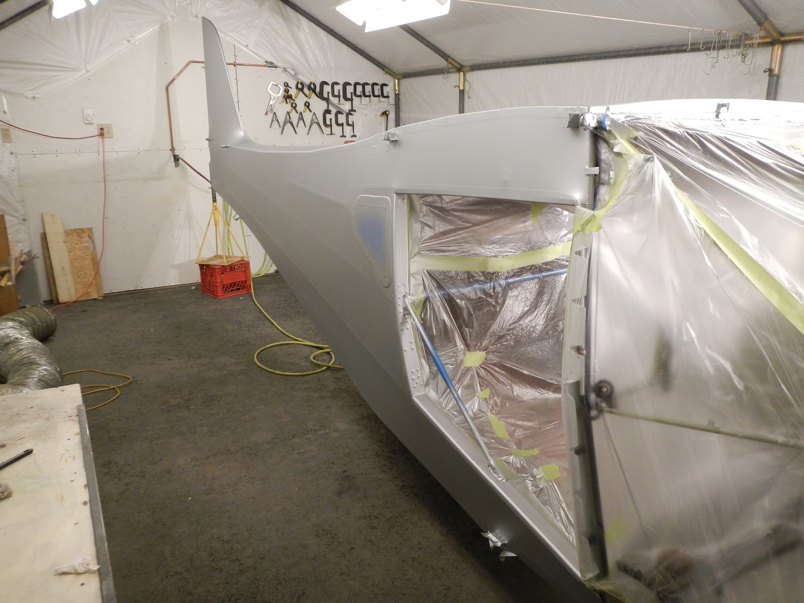

All the remaining little blemishes are wet sanded with 400 grit paper as well as the edges of all the tapes, gussets and doilies, and any place where significant sanding is needed is recoated with PolySpray.
Fuselage is now ready for the final cross-coats of Poly Spray.

Between coats I took care of some other tasks. I'll need the inspection plates and other small parts to use up any mixed top coat so they need to be ready.

Also finally got around to riviting the boot cowl together

With some new camlock springs.
October 2015
Continuing to install various parts on the fuselage prior to commencing the covering operation. Basically anything that can be installed or at least fitted prior to fabric is a little easier at this stage.


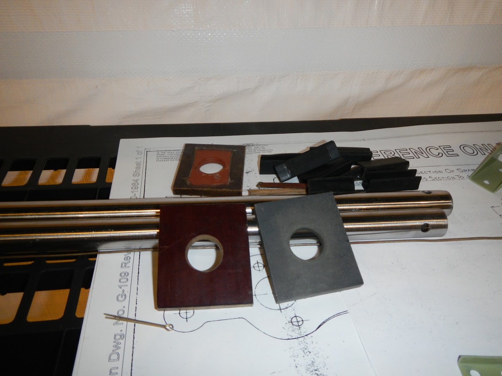
To install and rig the cable assembly, I need the control shafts and wheels. One of the phenolic bearings was ok but the pilot's side was worn to the point where the control wheel was sloppy. Fortunately I had a piece of 1/4" phenolic I've been saving for just this purpose.

Shafts installed temporarily

It was bound to happen.... I needed to open up one of the pulley mounts a little to accept the new pulley and when I did the weld broke. One of the nice things about TIG is a small weld like this can be done without negative effects to the surrounding components.
Wheels, shafts, sprockets, pulleys and cable assemblies installed...


...and tensioned.
Because of the configuration of the control 'H' frame and cable pulleys, aileron cable tension changes depending on the position of the elevator control. Rigging therefore consists of centering the control wheels, centering the bridal link and setting minimum cable tension with the elevator in the mid position. The result is a max tension of about 20lbs with the elevator in the full up or down position, and a minimum of about 5Ibs at the mid point.
 To fabricate the fuel line for the aux tank, the main tank needs to be in place.

Also needed is the shutoff valve. Both are rebuilt at this time.

 The replacement fuel line follows the original routing and adel clamps hold it securely so no possibility of chafing
or interference with the aileron cable.
The mount, fabricated earlier, is secured in place and replacement fuel line attached.

I was missing one of the four shackles that holds the seat "spider" and managed to find one at Oshkosh. Not that these are particularly difficult to find, but they're not inexpensive! Anyway I got a good price and saved on the shipping (that is of course if we consider my flight to OSH as a sunk cost :)

The side rod on the left is about an inch shorter (due to the fuselage diagonal) than the one on the right, and it's easy to mix them up resulting in a crooked seat!
Note also that the seat-belt attachment and support rod go around the cross-tube and not just the loop. (This is important!)


The hat shelf needs to be covered before installation so thanks to Thunder Bay Aviation I sourced some excellent quality glare shield fabric

 Fabric is attached with 3M hi-tack and then I can't resist the urge to offer up the spruce headliner trim:
and install in place.
Repairs to the floorboards consists of filling the various extra screw holes with rivets,


and finally some "bling," epoxy primer and urethane topcoat.


A spruce mount is fabricated for the VHF transceiver antenna and the antenna attached


The original attach angles are replaced with newly fabricated replacements

The idea is that the channel riveted to the lower panel fits snugly over the floorboard angles and the upper panel attached to the seat support frames.
I will eventually cover it with the same fabric as used on the hat shelf and glareshield.
There are many small parts that were originally cadmium or zinc plated, that have long since lost there corrosion protection. I've been gathering and cleaning these parts in anticipation of doing some DIY plating.


Then the "plating shop" is fired up.
Cad plating is a thing of the past due to improved environmental restrictions. Years ago I'd had success with electroless nickle plating on a Grumman Goose. It is a relatively simple and safe process so this is what I chose for the small parts.

The results....
Perhaps a bit more bling than I had hoped but complete coverage inside and out and more durable than cad or zinc.

After removing the latches for repair and plating, I continued cleaning up the upper cowlings.


July 2015
One last thing to do before epoxy priming the fuselage was replace the copper cable fairleads


The control 'H' frame is stripped inspected primed and top-coated with black urethane.
At this point I also decided to order all new pulleys (with bearings instead of bushings). There was an "ouch" factor associated with this as our Canadian dollar has taken a beating recently so all parts have increase 20%.


Some black Imron left over so applied non-slip to the rudder pedals.


One of the door threshold channels was broken, this one wasn't, but I fabricated doublers for both as this is an obvious week point.


In some areas the shop heads need to be flush to maintain clearance to the fuselage tubes. So a half countersink is cut and slightly shorter rivet used.


Eventually happy with the way the doors hung, but many more test fittings to come as the doors were reworked.

Other stuff:
New cable fairlead bushings turned from Delron

Wherever possible I have and plan to install nuts or nutplates, or at least tinnerman nuts as I think self-taping screws are less than ideal for aircraft use.

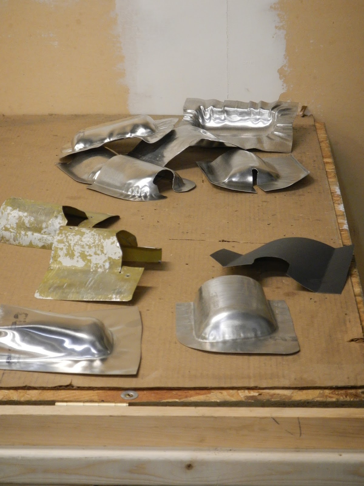
More sheet-metal work
I figured it was less risky to roll the fuselage upside down when there's no fabric on, so decided to continue with repairs and fabrication of all the fuselage components. In addition, the door frames also support the boot cowl so fitment needed to be checked. The boot cowl impacts windshield location which affects wood fabrication on top of the fuselage and the door post covers. In short one thing leads to another.
check out the quality paint job(s)... I guess the 1960's paint shop wanted that fuel placard to stay on :)


The lower half of the boot cowl was in rough shape, holes, cracks and deformations especially around the landing gear trunnions.
so I decided to make a new skin.


Test fitting
 New stringers were fabricated for the boot cowl too


These covers were originally formed from very soft material, bent back on itself 180 degrees to form the slot for the windshield. Problem with that is that it's virtually impossible to get a good seal/fair between the plexiglass and aluminium, as the material has no memory.


And obtained a good result


Have not purchased one yet but this is where the ELT will go


Hat Shelf
The baggage compartment of CLR had been "upgraded" which is to say there was nothing left of the original factory installation. I searched high and low but was unable to come up with any detailed information on the what the factory hat shelf, headliner and baggage compartment looked like on BC12D aircraft with these particular style D windows. To be honest I'm still not sure what it's going to look like as the headliner is not yet fitted.
Anyway I came up with a design that I believe to be consistent with the original and is also removable (without un-gluing anything) for full access to the empenage for inspection and repair.


Eventually the baggage compartment will attach to the spruce cross member with snaps


Headliner
First up, new bows were needed. The originals looked like they came off of an oversize baby carrage or something. Heavy rusty iron things that had no business being anywhere near an aircraft! Importantly, they also failed to make use of all the available headroom.
I ordered 2024 T3 3/16 OD tubing and fabricated three new bows


The difficult part is how to deal with the windows.
I have received the replacement headliner but not tried to install it yet. When I get back from OSH....

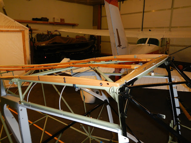
Some of the fuselage wood was serviceable but no point in half measures at this point so all new parts are fabricated from sitka spruce.
Tube radii are cut after trial and error setup of the table saw with scrap test pieces.

Wing root rib is used to check the profile of the wood parts.


new T nuts installed/epoxied in the forward spar carry-through.
In the background is the windshield cap strip which I will remake once the fabric is on.


In with the new and out with the old
Stringers
The D window configuration of CF-CLR effects the length and location of the stringers. Serfing the web for photos reveals that stringers have a significant impact on the final appearance of the aircraft, especially if they're done wrong. And for every photo, there seems to be a different configuration! (as far as I could tell by visualizing covered aircraft)
The two top and two bottom stringers were in good condition and someone had done a nice job of fabricating them from wood, presumably during the last recover. I had two short aluminium stringers that looked to be original and two longer (but clearly not long enough) aluminium stringers of typical aftermarket material.
Regardless of how I configured the four side stringers, I could not achieve an adequate result. The stringers obviously give the fuselage its shape, but they also ensure the fabric makes contact with structure where its supposed to, and provide adequate clearance where having the fabric touch tubes etc. is not desirable. Airflow is also a consideration ie I think we want the lines to be close to the straight and level airflow.
So, I used construction string to help visualize how the fabric will look and where it will contact structure.

After spending far too much time on this issue, I settled on this configuration
 Flutes are used to radius the ends of aluminium stringers.
 Four splices are required and some wood spacers just aft of the baggage compartment.

 Etch and alodine prior to epoxy primer.
Assembly
After assembling and disassembling various aspects several times, I finally got to final assembly.
The D window configuration of CF-CLR effects the length and location of the stringers. Serfing the web for photos reveals that stringers have a significant impact on the final appearance of the aircraft, especially if they're done wrong. And for every photo, there seems to be a different configuration! (as far as I could tell by visualizing covered aircraft)

The two top and two bottom stringers were in good condition and someone had done a nice job of fabricating them from wood, presumably during the last recover. I had two short aluminium stringers that looked to be original and two longer (but clearly not long enough) aluminium stringers of typical aftermarket material.
Regardless of how I configured the four side stringers, I could not achieve an adequate result. The stringers obviously give the fuselage its shape, but they also ensure the fabric makes contact with structure where its supposed to, and provide adequate clearance where having the fabric touch tubes etc. is not desirable. Airflow is also a consideration ie I think we want the lines to be close to the straight and level airflow.
So, I used construction string to help visualize how the fabric will look and where it will contact structure.

After spending far too much time on this issue, I settled on this configuration


Assembly
After assembling and disassembling various aspects several times, I finally got to final assembly.
A KISS trim indicator is fabricated


One of the failures of the previous covering job was the wood parts moving as the fabric shrunk. This will not happen on CLR because they are bonded in place with PRC.
 Lower wood parts installed. The PRC will also prevent chaffing between the wood and steel so reduce potential for corrosion.

 There was no transition between the fin and fuselage when I dismantled the aircraft but there is supposed to be one. So a new one was fabricated from 6061 T6 tubing.
 Top and bottom installation complete... glued and screwed.
 The transition discussed above worked out well.
 Dab of PRC at every contact point. The koro seal is really just to hold the parts in place until the adhesive cures.
 Left stab and elevator is temporarily installed so the trim system can be installed and rigged. Construction string is used to take the tension off the cable/spring to adjust the crank and tab actuator.
Will all need to be done again once fabric is on but I now know I can get the correct travel of the tab.

Elevator and rudder cables need to be fabricated and installed
 I used the old cables as a starting point

But cut to size only after confirming correct rigging could be achieved.
Rudder has 26 degrees left and right.
 Rudder pedals and 'H' frame installed
 New cables in and rigged so no surprises after fabric. I can also now record the location of the fairleads where the rudder cables will emerge from the fabric.
 Once happy with the flight control preliminary rigging, the side stringers are installed.
 Koro seal and PRC again. The poly tubing prevents the relatively sharp edge of the aluminium from cutting the lacing.
On later aircraft Taylorcraft used springs to hold this type of stringer in place but the springs rub the paint off leaving the tube exposed to the elements. Couldn't see going to all this trouble only to have the primer rubbed off so came up with this kinder gentler solution.
 Wood spacers bonded in place.
Yummy new pullies installed
 So I need to do battle with the headliner once again to pre-fit it prior to beginning fabric work. Not looking forward to that job. Other than that I will pre-fit the seat sling, baggage compartment and shoulder harnesses. Then I believe the fuselage is finally ready for covering!


Starting out with a small repair, the clips that attach the lower fuselage wood had been bent and straightened to the point where they were all cracked or broken
So new ones were fabricated

and welded in position.
 I had replaced the lower left aft logeron back in the
80s. The lower right had an external sleeve which was pitted and so was
the original tube. I decided to cut it all out, all the way back to the
lift handle to ensure all the internal as well as external corrosion was
removed.
I had replaced the lower left aft logeron back in the
80s. The lower right had an external sleeve which was pitted and so was
the original tube. I decided to cut it all out, all the way back to the
lift handle to ensure all the internal as well as external corrosion was
removed.
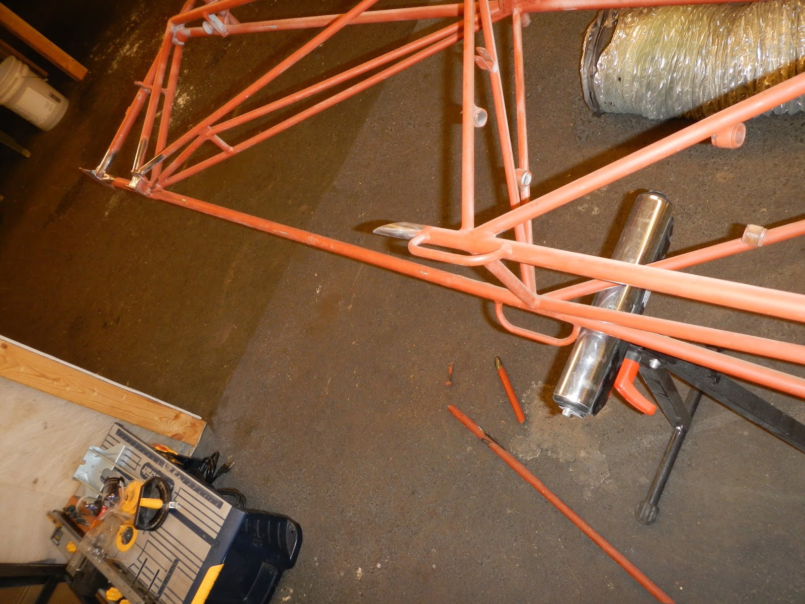
 While waiting for delivery of 3/4" tubing,
I busied myself with the chore of cleaning off all the red oxide primer.
While waiting for delivery of 3/4" tubing,
I busied myself with the chore of cleaning off all the red oxide primer.
 End of day two...


The internal sleeve for the longeron splice is turned from 090
wall thickness tubing for a "snug" fit.


 Silver sharpie works well...
 Once the tube is close enough to fit more or less in place, final trimming to get the right spacing at the splice and a close fit around the rudder post.


One of the failures of the previous covering job was the wood parts moving as the fabric shrunk. This will not happen on CLR because they are bonded in place with PRC.


Will all need to be done again once fabric is on but I now know I can get the correct travel of the tab.

Elevator and rudder cables need to be fabricated and installed


But cut to size only after confirming correct rigging could be achieved.
Rudder has 26 degrees left and right.


On later aircraft Taylorcraft used springs to hold this type of stringer in place but the springs rub the paint off leaving the tube exposed to the elements. Couldn't see going to all this trouble only to have the primer rubbed off so came up with this kinder gentler solution.


March 2015
In February we were welcomed home by a significant snow storm and very cold temperatures. Work on the tailplane created the need to get the fuselage into the hanger. I had media blasted the fuselage back in 1990 and faced with a move, I spray-bombed it with red oxide primer as a "temporary" corrosion prevention measure. After two years in unheated storage, four years in our garage in BC, and seventeen years hanging over our vehicles in our garage here in Thunder Bay, the red oxide did a remarkably good job in protecting the steel.... and it wasn't near as easy to remove as I thought it would be.Starting out with a small repair, the clips that attach the lower fuselage wood had been bent and straightened to the point where they were all cracked or broken
So new ones were fabricated
and welded in position.
 I had replaced the lower left aft logeron back in the
80s. The lower right had an external sleeve which was pitted and so was
the original tube. I decided to cut it all out, all the way back to the
lift handle to ensure all the internal as well as external corrosion was
removed.
I had replaced the lower left aft logeron back in the
80s. The lower right had an external sleeve which was pitted and so was
the original tube. I decided to cut it all out, all the way back to the
lift handle to ensure all the internal as well as external corrosion was
removed.
Tube
is cut at 30 degrees in anticipation of an internal sleeve splice.


End of day
4.


Using
the cut out tube to get a good match of the angle on the replacement tube.

I
only had one piece of tubing so I experimented with a piece of scrap first to
get a visual reference.


Ready to be tacked in place


Going over every inch of tubing, at least twice, made for a good inspection.
Other than the lower tube and the clips mentioned above, I found one unfinished weld and some minor tube deformations.......
which I took care of with my knockometers.
Cleaning clusters, oh joy. Here I found a Taylorcraft stamp.

So the fuselage is ready for final prep and primer along with the tail feathers which should happen in the next couple of days. Then fuselage pre-build prior to fabric. No doubt many other parts to be found cleaned and repaired along the way.
You did a beautiful job on clr.All the best I am doing my tcraft at the present time appereicate the information you posted. Thanks Monty s. Ame.
ReplyDeleteYou did a beautiful job on CLR. I am doing my tcraft at the present time Thanks for all the information you posted. Monty S AME.
ReplyDeleteyou did a wonderful job rebuilding clr. I am rebuilding a traft reg suc. All the best Monty.
ReplyDeleteThis post is an exceptional mix of valuable insights and engaging writing! I admire how you addressed such a complex topic with clarity and depth. Your unique perspective not only enriches the discussion but also inspires further thought. Thank you for sharing your knowledge—I eagerly anticipate your future articles!
ReplyDeleteCloth Tapes
Enrgtech
Thank you. Glad you found the info useful.
ReplyDelete