July 2018
I had a choice... put the wings on before the headliner and enjoy easy access for aileron rigging and turnbuckle saftying or, put the headliner in while the wings and struts were out of the way. I chose the latter and in hindsight I think its really six of one, half a dozen of the other.
Anyway, I secured the bows in place, with the headliner hung from them.
Note: refer to the Fuselage section 2015 for details on headliner pre-fitting.
Rather than depend soley on adheisive, I added a couple of snaps at the front top corners and picked up the trim indicator attach screws inboard.
Next the aft bow is pulled aft (actually tied to the top fuselage stringers) with stainless lockwire.
My top corner mods worked out ok.
The 040 aluminium strips were a bit of a pain to thread into the hem but all ends up good
After gluing the fabric to the D window frames and hat shelf, three wood trim pieces go in and further secure and tension the headliner.
I added a couple of small pieces of fabric to finish off the top corners,
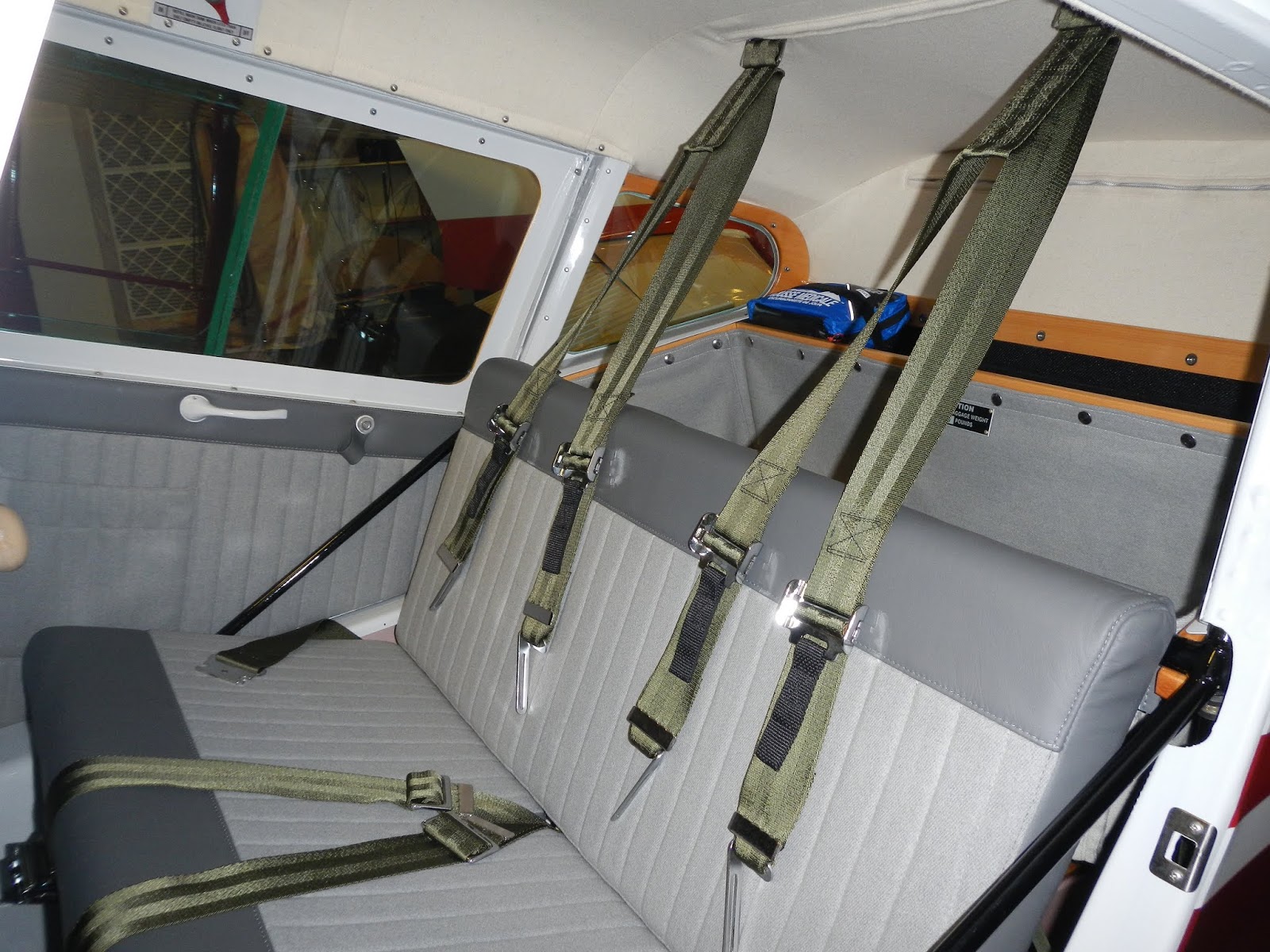
install the shoulder harnesses, and
job done.
Up on top of the spar carry-through, the T nuts are located and fabric cut in preparation for the windshield.
As I picked up the windshield I noticed another scratch.
1500 grit wet paper is used to blend out the damage.
Then, believe it or not, Mothers aluminium polish buffs the plexi back to a good finish.
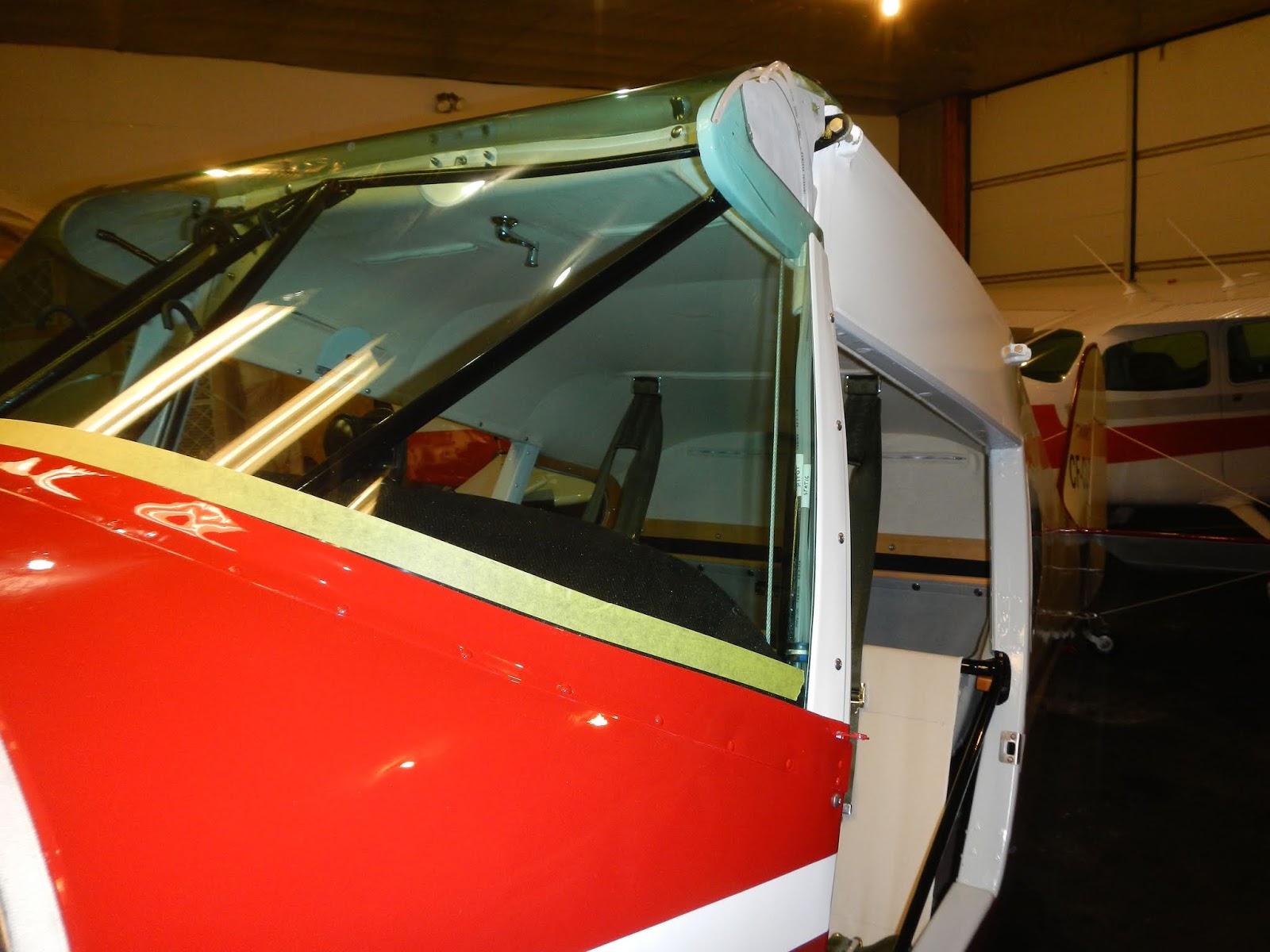
I spent yet more time trimming the windshield, mostly to get the height right.
A new top strip is made from 2024T3 .032"
In retrospect, I think it would have been worthwhile to make a step in the wooden spar carry-through so that the windshield would sit flush.
Anyway this is the original configuration.
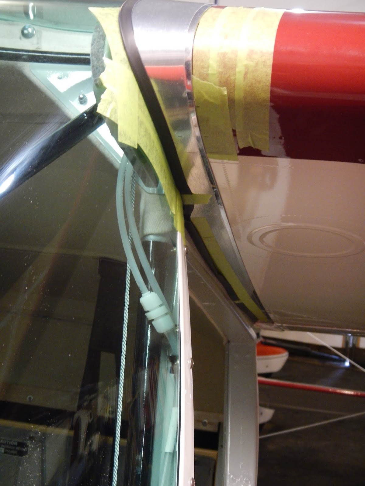
I put abrasion tape along the joint beyond the edges of the cap strip.
After paint, the cap strip goes on for good. I used a dab of clear silicone on each screw.
With the windshield installed it was time to run the A65. The first run revealed a problem with the Stromberg, actually with me....
I somehow managed to get an extra washer under the float valve seat which messed up the float level.
Note I have the 3lbs hammer ready just in case! :)
If you've watched the video you know the second run was better, but the throttle cable failed and the crankshaft seal had a small leak.
I rigged up "dino" to assist with wing installation.
Once the hoist positioning is right, the wing can be positioned slowly and with relative precision.
Still a stressful operation, but happily...
all went well.
The aux tank connection was achieved, with some fiddling, but without having to open the inspection ring on the lower surface of the wing.
And mostly just cuz I know its there, I installed a cover.
The windshield lined up reasonably well considering the number of variables.
Wing rigging requires levelling.
Motorcycle jack, a couple of milk crates, a cargo strap
I drilled and tapped my spirit level to measure the wing wash out.
Engine hoist employed again to position the trailing edge while making adjustments to the rear struts.
I leveled the aircraft laterally with a lazer across the front strut attach bolts, and then did final rigging of the tailfeathers
Jury struts installed
Pitot line connected.
The static "port" is just the end of the tube stuffed into the wing. I put a port inside the tube before feeding into the wing.
There is not much room between the wing and fuselage so to get gentle bends I installed matching grommets in the false rib and pushed the pitot line in during wing installation.
The new crank seal arrived and upon removal of the old (new) one the spring I think had come out of its groove.
As is typically the case I paid more attention the second time around and noticed that there is actually not much of a groove. The spring pops out quite easily if the seal split is not kept aligned.
To be sure, I spent some more time polishing the crank with 400 paper and light oil.

Then 180 grit paper to put the so-called "helix" on per the Continental service bulletin.
I received a new throttle cable but unfortunately it didn't fit. After some back and forth with McFarland, I ordered another cable. Specifically one meant for a Cessna 206.
Meanwhile I dug out the old wing root fairings to use as patterns.
I couldn't find structural machine screws long enough so I joined two together with a piece of steal tubing.
The originals are two strips spot welded together. I cut some from 2024 T3 .020" x 12'
The bend around the trailing edge is at an angle and the easiest way to get it is marking it while in place.
Formed around an AN4 bolt.
The steal fittings are salvaged and media blasted.
I picked up the hole locations from the old parts
Old clamped around the outside of the new strip.
Where there is a gap, I marked the old strip using a 6" ruler, then transfer the line to the new part.
To use solid rivets the holes must be dimpled.
There is not much room for the screw so I cut a small countersink on the inside to keep the profile of the shop head low.
Finished off the trailing edge and lap joint.
Now it's trim and fit time... trim a little at a time, on and off and on and off....
Finally, make sure there's enough room for the neoprene channel.
I also formed a slight flanged edge where the strip sits flat.
Originally the fillet fairings were nailed to the wood strip through the fabric. Not a good or particularly effective means of attachment.
The fairings can't really go anywhere if they're a good fit in the space, so I put 'P' section on the inboard edges and made spacers with vinyl tubing outboard, then a dab of Proseal under the flange where the nails used to go.
Seems I didn't take any photos of the aileron installation, but the cables need to be fed through the gap fairings first!
After paint the root fairings are installed (abrasion tape is used to protect under the edges).
The throttle cable arrived and looked to be a good fit, except its larger diameter and overall more substantial construction made it difficult and not really practical to follow the original routing (under the exhaust and over the oil tank).
So the routing was changed to a far more direct path over the exhaust and the cable is long enough to allow for exhaust shroud removal without disturbing the throttle control.
Unfortunately the C206 firewall is apparently further aft so the fairleed on the cable is in the wrong place. As an alternative I used this grommet edging coupled with Proseal. The old hole is plugged with a stainless tinnerman washer and machine screw.
It was necessary to fabricate a fork and new bracket
I used .100" chromoly for the fork and 050" for the bracket.
The tab ensures the bracket cannot rotate and allow the throttle to come out of rig.
There is a clear path for the cable, but I added an adel clamp for good measure to keep the cable clear of the exhaust and engine mount.
The C206 cable has a 10-32 pushrod and flex joint which all works well for the Taylorcraft installation.
I put a 1/2" spacer at the panel end. This moves the friction adjuster out well clear of the bottom of the instrument panel.
Lastly, I salvaged my original Taylorcraft knob and installed a 1/4-20 heli-coil to make it fit the new cable.
Like butter!
The seats and door panels arrived back from Thunder Bay Avtech right on schedule.
I wanted door pulls to make it easier to close the doors from inside. I made a couple of U channels with nutplates and secured them to the inside of the door panels with Proseal.
On the inside I made a couple of 'buttons' to finish off the leather door-pulls.
The door panels windows and window frames are all a snug fit but go together well.
It had to happen...... I dropped the pilot's side door!!!
I had it hung in place with the pins in but not secured. Next thing I know it cartwheeled onto the floor, landing on the top aft corner.
Once I calmed down, I was able to straighten the dog-eared corner, feather the damaged paint and mask it off. I just sprayed the top corner. Thankfully it's not a high-vis location. (sh*$&*t!)
Couple of other loose ends...
The cowling intake grills
the upper cowl latches. I cut a small countersink for the shopheads cuz there's not much space between the cowling flanges.
The original steel rivets were lower profile but still ended up chafing into the aluminium flange.
masking tape protects the nickle plating and the rivet heads.

Nose bowl and top cowlings fitted.
Some minor trimming of the front baffle seals required.
And the lower cowling goes on and fits well. Phew!
Oh, I decided to use #8 countersunk machine screws and nuts for the lower latches. There's room for the nuts and this will allow easy removal if repairs are required in the future.
Couple of little gap fillers to block the openings necessary for the upper cowl hinging.
And a strip of baffle material to act as a rub strip.
Prop cap is sanded by hand first with 400 grit paper, followed by 1500 grit on the random orbital sander, then buffing wheel with various compounds and finally jeweler's rouge.
Had to do it!
Managed to secure some scales from a neighbour.
Station information is not complete in the various factory publications so a plum line is dropped from the leading edge of the wing to measure actual arms.
Your results will vary!
I use the engine hoist to lift the mains on and off the scales.
822lbs without pants.
Finally the wheel pants go back on and...
The seats go in.
Done!
June 2018
While waiting for 2" tape for the right wing, I continued assembly of the fuselage components.

There was a collection of tasks that ideally are best accomplished before the boot cowl installation.
Plumbing needed to be sorted out.
CF-CLR had soft aluminium and copper tubing from the instrument panel through the firewall to the engine with no breaks (but many bends and re-bends, chafe and cut points.
I decided to replace all.
I used 5052-0 tubing.
First the vacuum connection from the venturi to the turn & slip indicator.
Primer lines, From the primer to the firewall.
Connections to the primer are SAE type flairless fittings.
Craft card is used to get the position of the firewall fittings.
Oil pressure, gauge to firewall.
Also connected and secured the ships wiring for the radio package, which includes a wire for RS232 serial input from a GPS for ADS-B out if I decide to add it later.
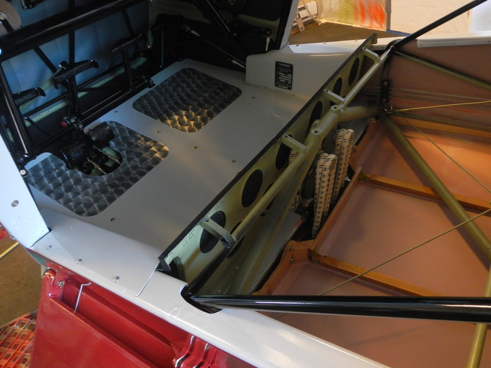
Installed the pitot and static lines.
I included wiring for a right side PTT just in case, and secured the mag wires. Then the right map box goes in.
(altimeter failed the leak test and needed to be sent for certification anyway).
The center belly panel goes in. 1/4" sound absorbing material will hopefully reduce drumming.
Dusty bungie covers go on. They've been on the shelf for a long while.
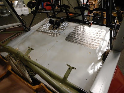
Floor panels next. Some struggling to get the holes to line up but eventually it fits.
As is typical with these old aircraft, there were many extra holes in the firewall. No idea what they were for, but I chose the ones that seamed to be in the best positions for each of the systems I had to accommodate, and plugged the rest.
To facilitate installation of the cabin heat duct and lower cowling mount, and to make them easily removable, I fabricated a doubler with 6-32 nutplates.
.
There's not much room between the firewall and the lower fuselage cross tube but enough for the nutplates and correct length screws
This also solves the problem of not being able to reach around the boot cowl to buck rivets!
Positions are marked and holes cut in the firewall blanket.
The fuel filler neck doughnut is also installed
The blanket is secured around the edges with contact adhesive and sound foam added.
The boot cowl is ready for installation, but first there area couple of other things to take care of.
Switching attention to the tail feathers, the rudder is installed and I figured the stab would get in the way so went ahead and installed the registration letters and Taylorcraft decals.
Exciting!
It was still cold in the hangar so the spotlights were used to warm things up a bit.
Also poked holes for the access panel screws and realized the fabric I wrapped around the fuselage tube would be exposed to UV and did not have Polyspray coverage, so I brushed on six coats.
With this configuration of the panel and aluminum frames (in lieu of the original plastic ones) it's not possible for any aspect of the panels to interfere with elevator operation. (there is an AD on this)
Flying wire fittings installed
I leveled the fuselage laterally, checking across the engine mount location and spar carry-through, and set preliminary rigging of the tailplane.
Left elevator goes on next and the trim cable is eased onto the pulley. I used a small cord inside to release some of the tension from the trim spring to aid this operation.
I missed by a few degrees on the first attempt but the second try got the 25 degree down and 30 degree nose up specification.
Right elevator is installed and the cables connected and safetied.

Eyebolts are on order for the tailwheel spring connections but otherwise the tail is done save for the duel inspection of the controls.
After a final check to make sure all cotter pins and safety wire etc. were in place, the boot cowl goes on.

I decided to use stainless hardware.
I also used nylon washers. This is something I did on my 172 and has worked well.
The nylon prevents the screws from fretting off the paint and then working their way into the relatively soft aluminium of the cowl.
The doughnut was a bit of a struggle as it doesn't end up square with the tank neck. Some material had to be removed from the inside of the doughnut so it would sit nicely.

Cables etc. are routed through and tidied up a bit.
Typically, the fuel outlet was not centered in the firewall opening so the options are pack it full of zinc chromate putty or similar, or make a cover.
Proseal to bond it in place and seal around the fitting.

Almost ready for the engine, but first I'll connect the cabin head cable while access is easy.
To get full travel I had to remove some of the outer cable. Unfortunately the inner cable cannot be removed so the outer is carefully cut until it can be twisted off.
Then de-burred and all works well.
Finally the engine goes on!
Throttle gets a new bracket made from 4130 chromoly and is connected rigged and safetied.
I connected the mixture control, also with a new bracket. These stomberg mixture controls are a little odd, but the control will at least hold it in full rich!
Carb heat connected.
Main fuel line fabricated and installed.
Primer lines fabricated and installed along with the flex line to the carb and steel primer line to the intake manifold.
At this point I put a couple of gallons of fuel in the tank and checked everything for leaks and flushing/functioning of the primer system.
Mag wiring confirmed and switch tested again, then connected to the mags.
Note, I used shielded wire and the mag switch is not grounded to the aircraft frame. The shield is connected to the mag case and the ground terminal of the switch which effectively means the shields are only grounded at one end. Hopefully this handles any potential EMI issues.
Cabin heat flex duct installed.
Although it didn't have one originally, I installed an orifice type fitting for the oil pressure line which will serve to both dampen the pressure gauge and prevent rapid oil loss into the cabin in the event of gauge or line failure.
Flex connection to the firewall.
There was a need to prime the oil system.
The A65 tends to be difficult sometimes in this regard and I want to be sure I have oil pressure when she fires up for the first time since 1989.
I added an extra quart of oil so the tank was well over filled. With the pressure line disconnected, spark plugs removed and the prop installed temporarily, I pulled the engine through and after only a few seconds or so had oil flowing out of the hose.
I then connected a slave gauge and was able to get over 20 PSI, which I sustained for about a minute.
Then I reconnected the flex hose, loosened the fitting at the gauge, and pulled the engine through a couple more turns to get the air out of the tube.
That completes the bulk of the powerplant installation.
Back to the cockpit, I ran a wire for the pilot's PTT through the control column.
The control wheel is magnesium and particularly susceptible to corrosion. After taking the time to do a proper conversion coating, epoxy primer and topcoat I wanted to avoid drilling any holes. So I made a mount for the PTT switch and bonded it to the back of the wheel with Proseal.
With the switch connected I tested the com and intercom.
Next the old glare shield is put in place and marked up as a pattern.
New panel cut from 2024T3 .020"
Couple of trial fit & trims
I formed the edges a little to create some rigidity and a better shape.
Leaving ample clearance for the fuselage tubes so the panel can be removed and installed relatively easily.
Marked out and drilled mounting holes and holes for the compass,
and covered with glareshield material.
Done
Also covered the kick panel that goes under the seat leading edge, and
installed it, the fire extinguisher, and the small side threshold covers.
There are eight possible screw locations, I used four which seemed more than adaquate.
Probably ahead of schedule given it only has a year before recertification but I went ahead and purchased and installed the 406 ELT.
I measured and trimmed about 8" off the front of the seat sling, then glued it to the maple cross-member with contact adhesive.
As I rolled it I marked and punched holes for the structural screws.
Temporary installation 1 provided the location (height) for the baggage compartment snaps.
With the sling installed once again, the baggage "hammock" is offered up.
I purchased this baggage compartment from Aircraft Spruce. It's well made but unfinished of course and doesn't take into consideration the trapezoidal shape of the space, but provides a decent starting point.
To give some stability to the top I sewed in a length of webbing.
The two outboard aft snaps are installed such that some stretch is needed to snap it into place. The remaining snap positions are then marked and holes punched.
After putzing around with the supplied snap tool, I threw it in the trash and used my brake rivet tool.
Installed again to mark the remaining snap locations.
Baggage placard finishes the task.
The gear fairings go on next and fit well.
I use cyano glue to secure the rubber channel. Fast and secure.
Also added some leading edge abrasion tape were the fairing contacts the gear fabric.
The altimeter comes back from Overhaul.
A worthwhile addition is to use a little lacing to secure the instrument nuts. Better than chasing them around the cockpit floor.
The altimeter is the last in the static chain i.e. no T fitting, so it's easier to remove and install for the two year re-certification requirement.
Successful leak test this time. The Trig Transponder also provides a read-out of the encoder altitude it's broadcasting so a correlation/integrity test can be performed as well.
That little hand pump is good for 20,000'.
Sound material is attached to the underside of the glare-shield and
it's installed along with the compass.
Tidy up the seat sling para-cord.
and I put the old seat cushions in for a "seat fitting".... it's a little more cozy compared to what I remember! perhaps I got the sling too taught.
I had Nigel from Thunder Bay Aviation come by to have a look and we discussed the seats and door panels. The plan is to cut about 3/4" of both the seat cushion and back to create a bit more space.
I had an urge to install the wheel pants (thought it would be more convenient before the wings and struts are on).
The mounts and pants are positioned and then drilled for 3/16" structural screws and nutplates.
I added the rubber extrusions to protect the paint on the gear legs during removal and installation.
I made "cushions" from silicone baffle material.
Bonded in place with superglue.
This also allows for universal head rivets for the nutplates which is a little easier.
Finally washer-head structural screws and the AN5 bolts on the gear legs are torqued up.
Prop paint touched up.
I had taken time during the winter to do a dimensional check, inspect for corrosion and dress out all the minor nicks and scratches.
Next the headliner... oh joy!
December 2016
I'm using the heading "Final Assembly" as it might be used in a production environment, that is, the assembly of all the various sub assemblies and components into one BC12D. This in no way suggests that completion of the project is going to happen soon!
With all but the wings and ailerons painted I decided the next step would be to get the fuselage on its wheels. The longer it's on the rotisserie and tail stand, the higher the chance of damage. I also need the steel and casters for the wings, and having the fuselage safely on its wheels makes it easier to move around the shop.
Having said this, there were two unanswered questions nagging at the back of my mind, i.e. the location of the rudder cable fairleads, and the elevator trim push-rod opening.
So I opened one of the elevator inspection panels and opened the push-rod slot (with great anticipation and trepidation).
Then installed the trim tab and to my relief the alignment was near perfect!
So I went ahead and installed the rod and tab
There seems to be two options to secure the tab hinge-pin. One is to pin it to the elevator frame, outboard of the tab. The other options is to secure it to the tab skin at the root end.
I choose the latter as I felt having the pin rotating in the steel bushings attached to the elevator was better than having the aluminium tab moving relative to the pin.
Next I temporarily installed the rudder and cut the cable fairlead slots. This also provided relief and satisfaction as I couldn't have expected a better result.
Referring back to the fuselage section, I did not have the old fabric (I purposely trashed it as I removed it as I wanted to make sure I couldn't copy anyone else's mistakes!).
Continuing on, I prepared for installation of the Naugahyde fairleads.
Pleased with the result....
I also fished out the elevator and trim cables,
and installed and rigged the rudder stops.
Next the leaf-spring and tailwheel assembly.
At this point I realized I was missing a couple of spacers for the wheel so I turned a couple out of chromoly.
I wanted to plate them for corrosion protection.
So before I set up the plating bath again, The door strikers were on the to-do list.
The doors were installed temporarily again to mark, cut and fit the strikers.
Wheel spacers, washers and brake pins electroless nickle plated.
Strikers installed.
Tailwheel gets new bearings and seals,
and installed.
By the way, my intention is to leave inspection access openings unopened unless absolutely necessary. The lower aft inspection opening is one that can do more harm than good. An adequate inspection of the the area can be conducted from the upper panels so leaving it closed will keep out water and debris.
The leafspring bolt was easily installed from the upper access panel.
For no particular reason other than coming up with a list of fittings needed, I installed the venturi. The original doubler was inadequate (something I'd forgotten about and should have been done before paint), so I made a new one and bonded it in place with proseal.
I don't know if this was a factory option or if it was added in the field, but I think a turn & slip indicator is good to have so it stays.
The venturi got me thinking about instruments, fittings and the panel and I thought installing same might be easier before the main landing gear-legs got in the way.
So the panel gets crinkle black finish (which I believe is what CF-CLR had from the factory).
It is my intention to have a VHF transeiver with built-in intercom so I installed pilot and copilot headset sockets.
I also installed tinnerman nutplates for the map-box door hinges. I think originally there may have been clip-nuts, or perhaps more likely just Pk screws into the aluminium of the panel. But there is not very much space there and the screws would almost certainly end up jammed against the fuselage cross-tube (as evidenced from the marks I dressed out of said tube).
Compass correction card holder is attached in the approximate location shown on the Tcraft drawing.
The drawing also calls out two mounting screw locations in the lower outboard corners of the instrument panel.
There were no such screws on CF-CLR and it appears, based on an informal poll of the good people on the Taylorcraft forum, that at some point they were deleted by Taylorcraft (along with the tabs welded to the fuselage cross-tube).
What this means is that the whole panel, instruments, and at least 75% of the map-boxes and contents, are secured by just 4 No 6 screws.
Anyway I upgrade to 6 # 8 washer-head machines screws and used clamps as shown.
The mag switch and controls are installed....
and the rest of the instruments plus the map-box doors.
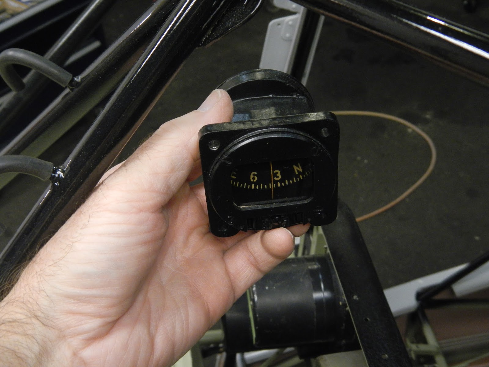
There are two options for mounting the compass. I always wanted to mount mine up on the windshield cross tubes.
However, as can be seen here, the steel tubes cause almost 60 degrees deflection.
I think this would be difficult if not impossible to compensate for so unfortunately I'll be sticking with factory option 2 i.e. the glare-shield mount.
As all Taylorcraft owners and pilots know, there is a bulletin requiring the installation of a positive means of preventing the fuel shutoff being pulled inadvertently.
The solutions in the field vary widely but the one I had could have definitely been a contender for a "furthest from acceptable" prize.
Anyway I had this galley door lock (I think it might be from a DC-9) floating around in my tool box since about 1980. It has a nice adjustable detent and red anodized finish.
Glad I never threw it away!
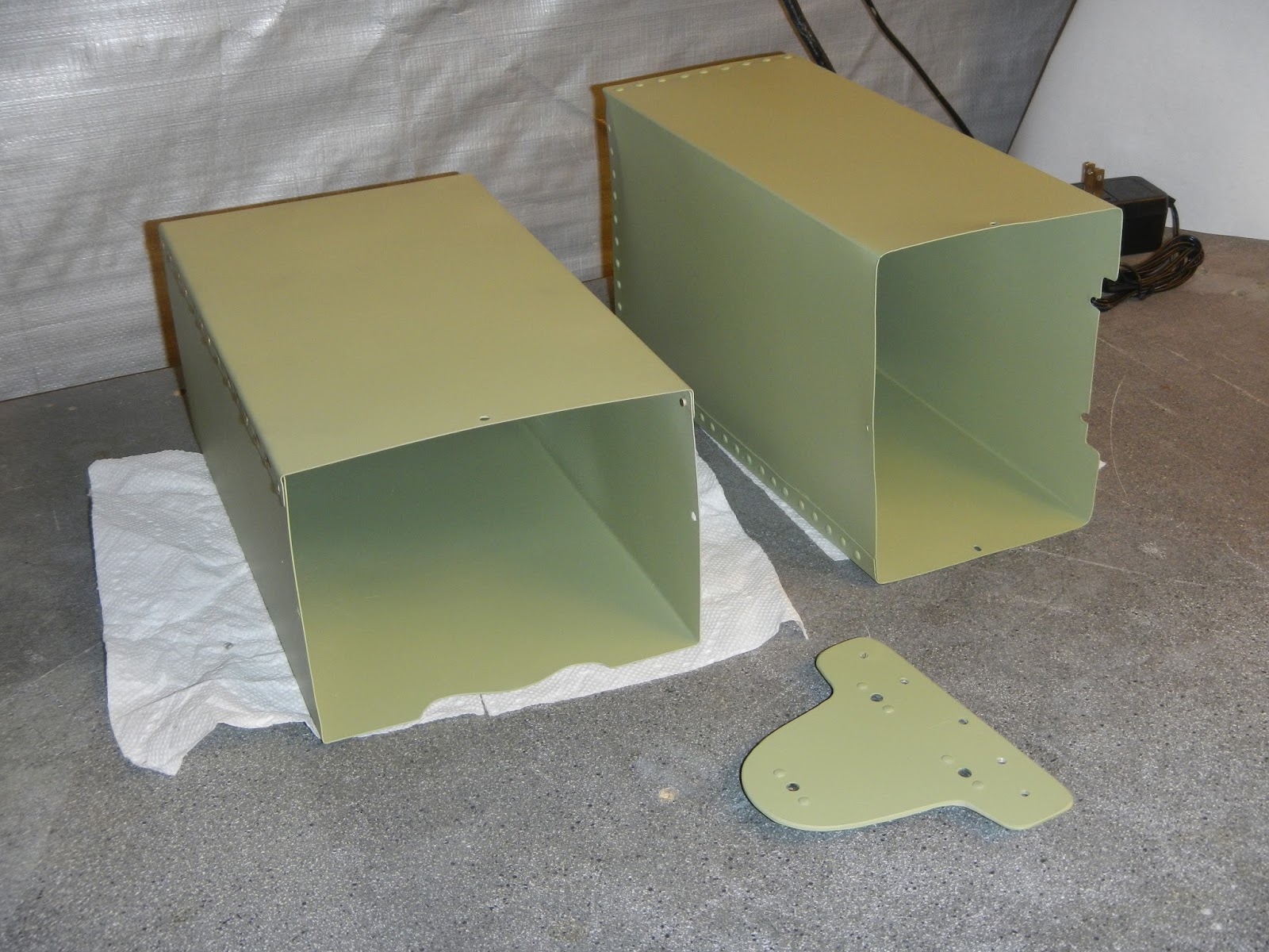
I only had one map box, so I fabricated a second.
Primed and riveted together, along with the compass mount (trimmed) and the existing map box.
After alodining the above parts, I also did the brake backplates, trying to get a nice even finish because they won't be painted.

The shinn wheel/brake parts break-out shows grease seals which don't seem to be available. There is not enough space for any commercially available seals that I could find so I made some felt seals and attached to the inboard spacers.
Felt is attached to the washer, and
the excess is then trimmed away.
The outboard wheel pant mounts get silicone washers.
Finally time to dispense with the rotisserie and install the main gear.
Some cleaning of paint needed but otherwise all fits well. I use a molybdenum disulfied-based grease in the bushings.
Bungee installation is tense, but straightforward if you have a good tool.
Standing on its own two legs.
I had one spring for the lower brake bellcrank. Tried to buy a couple but no success. So I purchased some 060 stainless spring-wire and made two replacements.
I don't know if what I had was original, likely not. I changed the orientation and radius of the hooks for easy of installation and spring positioning.
It's tempting to install the bellcrank, and then try to pull the spring into position. I expect it can be done that way but you risk scratching the paint or worse damaging the fabric.
A much easier way is to attach the spring first, then fiddle the bellcrank through the leg tubes and into position.
No tools required :)
The pull-rod holes were in the wrong place on the new back-plates so I trimmed them up about 1/4" each.
Then installed the adjuster locks.
Thanks to Marty on the Taylorcraft forum I didn't have to purchase 200 of these 80 degree screws for the brake backplates.
I did cut them, because two of the holes have the gear leg tubes behind them causing the screws to bottom out easily. I cut them all cuz there's no sense carrying extra metal around.
Before lubricating all the action points, the parts are assembled to make sure everything fits and moves as it's supposed to.
I check for clearances too. It's helpful if the shoes fit snugly to the mounts. I bent them by hand a little to ensure this was the case.
Originally the screws were punched to stake them in place. I used medium Locktite which will prevent them coming loose but allow for easy removal when needed.
The high spots needed to be removed from the new linings. This involved gluing a piece of emery paper to one of the shoes, installing the wheel and turning it back and forth while gradually winding in the adjuster.
I thought I'd made a find when I got tabbed washers from a tractor part dealer. But they turned out to be not good quality and too thick (could not get the cotter pins in), so I made a couple from AN970 chassis washers.
This had the advantage of a larger OD so I could make another felt dust seal.
After a final cleaning the bearings are packed and everything assembled.
The back-plate is "adjusted" to provide a close but rub-free fit.
The left cable ended up very close to the fabric. No practical solution to this as moving the welded-on clevis is not an option. So I applied a small piece of Teflon rub tape which will protect the fabric.
The pedal ends are terminated with turnbuckles. This will allow future adjustment of the cables.
For the first time in almost thirty years CF-CLR stands on its own three boots.


 Then 180 grit paper to put the so-called "helix" on per the Continental service bulletin.


 Nose bowl and top cowlings fitted.


 There was a collection of tasks that ideally are best accomplished before the boot cowl installation.


 Eyebolts are on order for the tailwheel spring connections but otherwise the tail is done save for the duel inspection of the controls.


 Cables etc. are routed through and tidied up a bit.


 The shinn wheel/brake parts break-out shows grease seals which don't seem to be available. There is not enough space for any commercially available seals that I could find so I made some felt seals and attached to the inboard spacers.


wow excellent job !! well done
ReplyDeleteIs it possible to get the brake linings rebuilt.?
ReplyDelete